
 Inverters are also called power regulators. The process of converting DC power into AC power is called invert. The circuit that can realize the inverting function is called an inverter circuit. A device that can realize the inverting process is called an inverting device or inverter. In a solar energy generation system, the inverter efficiency is an important factor that determines the solar cell capacity and the storage battery capacity. The breakdown of PV inverter will cause the PV system to shut down and this directly leads to the loss of power generation. Therefore, high reliability is an important technical indicator for PV inverters.
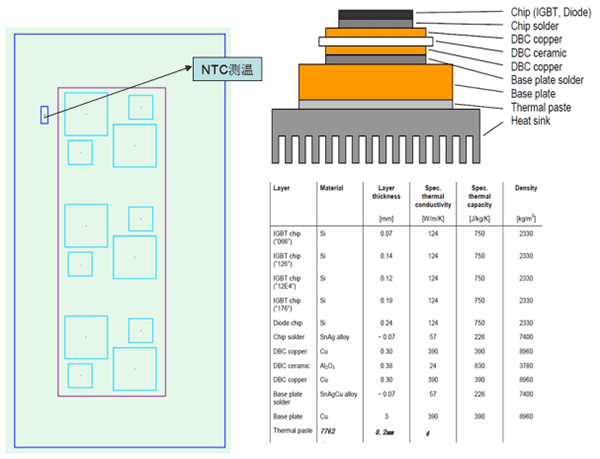
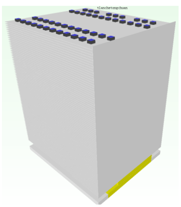 Heat sink parameters:


- Product techniques
- Skived fin heat sink
- Friction stir welded heat sink
- Heat pipe thermal module
- Water cooler
- Applications and industries
- Cooling solutions for electric car controllers
- Wind power converter cooling solution
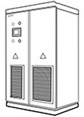
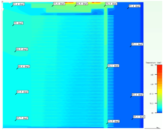
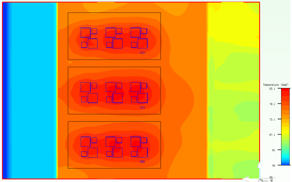
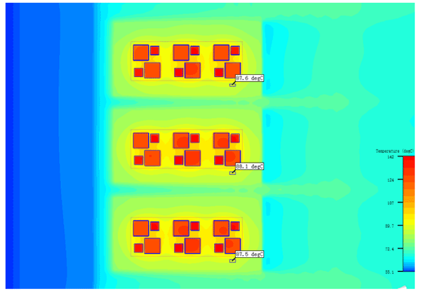
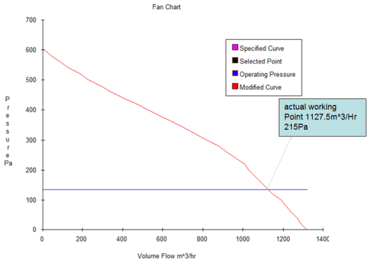
- PV inverter cooling solution
- Energy storage system cooling solution
-

Official account

Official website